JEE Main 2019 — Electromagnetism
Physics Electromagnetism questions from JEE Main 2019.
Other Years
142 Electromagnetism Questions from 2019
An alternating voltage $V(t)=220\mathrm{sin}(100\pi t)$ volt is applied to a purely resistive load of $50 \Omega$ . The time taken for the current to rise from half of the peak value to the peak value is:
Consider the LR circuit shown in the figure. If the switch S is closed at $t=0$ then the amount of charge that passes through the battery between $t=0$ and $t=\frac{L}{R}$ is: 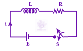
The electric field of a plane electromagnetic wave is given by $\vec{E}={E}_{0}\hat{i}\mathrm{cos}(kz)cos(\omega t)$ The corresponding magnetic field $\vec{B}$ is then given by:
The electric field of a plane polarized electromagnetic wave in free space at time $t=0$ is given by the expression $\vec{E}(x, y)=10\hat{j}cos(6x+8z)$. The magnetic field $\vec{B}(x, z, t)$ is given by ($c$ is the velocity of light.)
An electromagnetic wave is represented by the electric filed $\vec{E}={E}_{0}\hat{n}\mathrm{sin}[\omega t+(6y-8z)].$ Taking unit vectors in $x,y$ and $z$ directions to be $\hat{i},\hat{j},\hat{k},$ the directions of propogations $\hat{s},$ is:
Find the magnetic field at point $P$ due to a straight line segment $AB$ of length $6 cm$ carrying a current of $5 A.$ (See figure) $({\mu }_{0}=4\pi \times {10}^{-7}{\mathrm{NA}}^{-2})$ 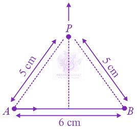
A moving coil galvanometer has resistance $50 \Omega$ and it indicates full deflection at $4 mA$ current. A voltmeter is made using this galvanometer and a $5 k\Omega$ resistance. The maximum voltage, that can be measured using this voltmeter, will be close to:
When the switch $S,$ in the circuit shown, is closed, then the value of current $i$ will be: 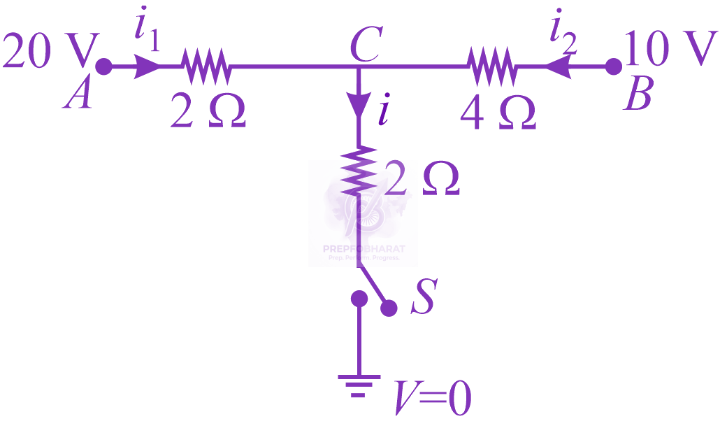
For the circuit shown, with ${R}_{1}=1.0 \Omega$ , ${R}_{2}=2.0 \Omega$ , ${E}_{1}=2 V$ and ${E}_{2}={E}_{3}=4 V,$ the potential difference between the points $‘a’$ and $‘b’$ is approximately ( $in V$ ): 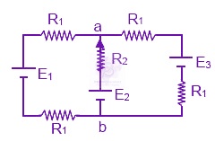
In the figure shown, a circuit contains two identical resistors with resistance $R=5 \Omega$ and an inductance with $L=2 mH.$ An ideal battery of $15V$ is connected in the circuit. What will be the current through the battery long after the switch is closed? 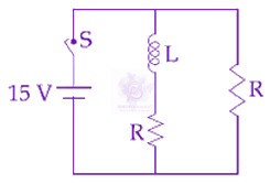
A circular coil having $N$ turns and radius $r$ carries a current $I.$ It is held in the $XZ$ plane in a magnetic field $B\hat{i}$ . The torque on the coil due to the magnetic field is:
A magnetic compass needle oscillates $30$ times per minute at a place where the dip is $45^{\circ}$ and $40$ times per minute where the dip is $30^{\circ}$. If ${B}_{1}$ and ${B}_{2}$ are the net magnetic fields due to the earth at the two places respectively, then the ratio ${B}_{1}/{B}_{2}$ is approximately equal to
An electric dipole is formed by two equal and opposite charges $q$ with separation $d$ . The charges have same mass m. It is kept in a uniform electric field $E.$ If it is slightly rotated from its equilibrium orientation, then its angular frequency $\omega$ is:
An electric field of $1000 \mathrm{~V} / \mathrm{m}$ is applied to an electric dipole at angle of $45^{\circ}$. The value of electric dipole moment is $10^{-29} \mathrm{C} \cdot \mathrm{m} .$ What is the potential energy of the electric dipole?
The energy associated with electric field is $({U}_{E})$ and with magnetic field is $({U}_{B})$ for an electromagnetic wave in free space. Then:
One of the two identical conducting wires of length $L$ is bent in the form of a circular loop and the other one into a circular coil of $N$ identical turns. If the same current is passed in both, the ratio of the magnetic field at the centre of the loop $({B}_{L})$ to that at the centre of the coil $({B}_{C}),$ i.e. $\frac{{B}_{L}}{{B}_{C}}$ will be
A transformer consisting of $300$ turns in the primary and $150$ turns in the secondary gives output power of $2.2 kW$ . If the current in the secondary coil is $10 A$ , then the input voltage and current in the primary coil are:
A $27 \mathrm{~mW}$ laser beam has a cross-sectional area of $10 \mathrm{~mm}^{2}$. The magnitude of the maximum electric field in this electromagnetic wave is given by: [Given permittivity of space $\epsilon_{0}=9 \times 10^{-12} \mathrm{SI}$ units, Speed of light $\left.\mathrm{c}=3 \times 10^{8} \mathrm{~m} / \mathrm{s}\right]$
A copper wire is wound on a wooden frame, whose shape is that of an equilateral triangle. If the linear dimension of each side of the frame is increased by a factor of $3,$ keeping the number of turns of the coil per unit length of the frame the same, then the self inductance of the coil:
A parallel plate capacitor is of area $6 c{m}^{2}$ and a separation $3 mm.$ The gap is filled with three dielectric materials of equal thickness (see figure) with dielectric constant ${K}_{1}=10, {K}_{2}=12$ and ${K}_{3}=14.$ The dielectric constant of a material which when fully inserted in above capacitor, gives same capacitance would be: 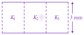
There are two long co-axial solenoids of same length $l$. The inner and outer coils have radii $r_{1}$ and $r_{2}$ and number of turns per unit length $\mathrm{n}_{1}$ and $\mathrm{n}_{2}$, respectively. The ratio of mutual inductance to the self-inductance of the inner-coil is :
The magnetic field of a plane electromagnetic wave is given by $\vec{B}={B}_{0}\hat{i}[cos(kz-\omega t)]+{B}_{1}\hat{j}cos(kz+\omega t)$, where ${B}_{0}=3\times {10}^{–5} T$ and ${B}_{1}=2\times {10}^{–6} T$. The $\mathrm{RMS}$ value of the force experienced by a stationary charge $Q={10}^{–4} C$ at $z=0$ is closest to
In a conductor, if the number of conduction electrons per unit volume is $8.5\times {10}^{28} {m}^{-3}$ and mean free time is $25 fs$ (femto second), it’s approximate resistivity is: $({m}_{e}=9.1\times {10}^{-31} kg)$
A proton, an electron, and a Helium nucleus, have the same energy. They are in circular orbits in a plane due to magnetic field perpendicular to the plane. Let ${r}_{p},{r}_{e}$ and ${r}_{He}$ be their respective radii, then,
In an experiment, electrons are accelerated, from rest, by applying a voltage of $500 \mathrm{~V}$. Calculate the radius of the path if a magnetic field $100 \mathrm{mT}$ is then applied. [Charge of the electron $=1.6 \times 10^{-19} \mathrm{C}$ Mass of the electron $\left.=9.1 \times 10^{-31} \mathrm{~kg}\right]$
A solid conducting sphere, having a charge $Q,$ is surrounded by an uncharged conducting hollow spherical shell. Let the potential difference between the surface of the solid sphere and that of the outer surface of the hollow shell be $V.$ If the shell is now given a charge of $–4Q,$ the new potential difference between the same two surfaces is:
A circuit connected to an ac source of emf $e={e}_{0}\mathrm{sin}(100t)$ with $t$ in seconds, gives a phase difference of $\frac{\pi }{4}$ between the emf $e$ and current $i$ . Which of the following circuits will exhibit this?
A positive point charge is released from rest at a distance ${r}_{0}$ from a positive line charge with uniform charge density. The speed $(v)$ of the point charge, as a function of instantaneous distance $r$ from line charge, is proportional to 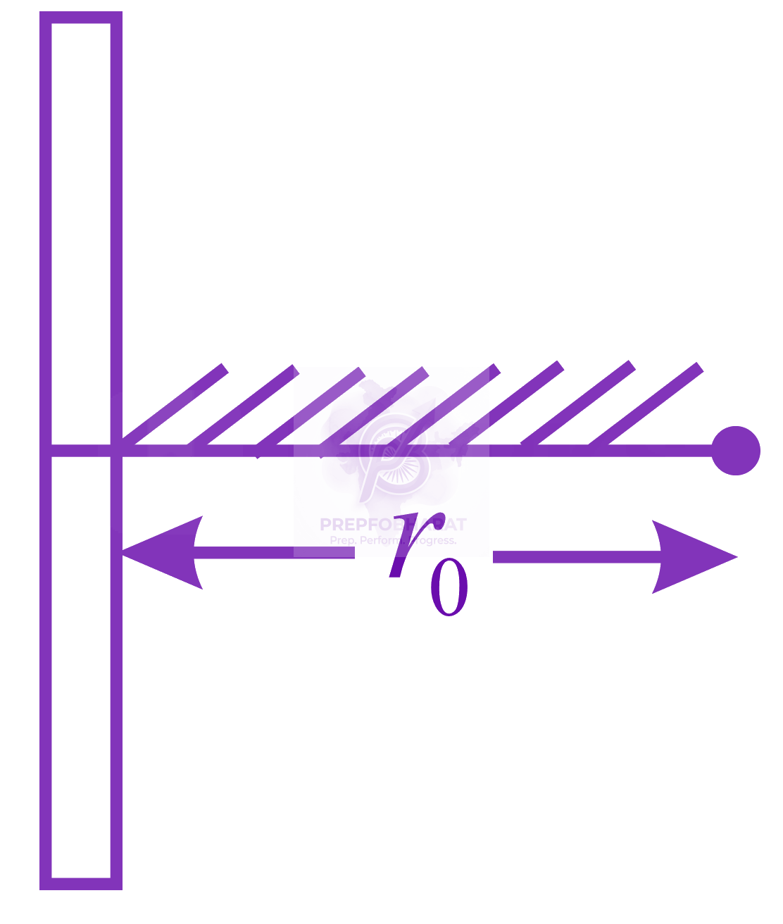
A plane electromagnetic wave having a frequency $f=23.9 GHz$ propagates along the positive $z-$ direction in free space. The peak value of the Electric Field is $60 V/m.$ Which among the following is the acceptable magnetic field component in the electromagnetic wave?
A bar magnet is demagnetized by inserting it inside a solenoid of length $0.2 m, 100$ turns, and carrying a current of $5.2 A.$ The coercivity of the bar magnet is:
A parallel plate capacitor is made of two square plates of side $a,$ separated by a distance $d (d\ll a).$ The lower triangular portion filled with a dielectric of dielectric constant $K,$ as shown in the figure. Capacitance of this capacitor is: 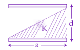
A plane electromagnetic wave travels in free space along the x-direction. The electric field component of the wave at a particular point of space and time is $E=6 V {m}^{-1}$ along y-direction. Its corresponding magnetic field component, $B$ would be:
Drift speed of electrons, when $1.5 A$ current flows in a copper wire of cross section $5 {\mathrm{mm}}^{2}$ is ${v}_{d}.$ If the electron density in copper is $9\times {10}^{28}{m}^{-3}$ the value of ${v}_{d}$ in $\mathrm{mm}{s}^{-1}$ is close to (Take charge of an electron to be $=1.6\times {10}^{-19} C$)
A thin strip $10 cm$ long is on a $U$ shaped wire of negligible resistance and it is connected to a spring of spring constant $0.5 N {m}^{-1}$ (see figure). The assembly is kept in a uniform magnetic field of $0.1 T.$ If the strip is pulled from its equilibrium position and released, the number of oscillations it performs before its amplitude decreases by a factor of $e$ is $N$ . If the mass of the strip is $50$ grams, its resistance $10\Omega$ and air drag negligible, $N$ will be close to: 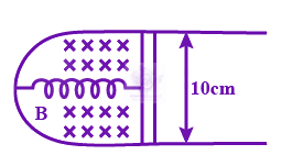
The Wheatstone bridge shown in the figure below, gets balanced when the carbon resistor used as ${R}_{1}$ has the colour code (orange, red, brown). The resistors ${R}_{2}$ and ${R}_{4}$ are $80\Omega$ and $40\Omega$, respectively. Assuming that the colour code for the carbon resistors gives their accurate values, the colour code for the carbon resistor, used as ${R}_{3}$, would be 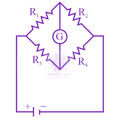
The magnetic field of an electromagnetic wave is given by: $\vec{B}=1.6\times {10}^{-6}\mathrm{cos} (2\times {10}^{7}z+6\times {10}^{15}t) (2\hat{i}+\hat{j})\frac{Wb}{{m}^{2}}$ The associated electric field will be:
A $20$ $\text{H}$ inductor coil is connected to a $10$ $\Omega$ resistance in series as shown in figure. The time at which rate of dissipation of energy (Joule's heat) across resistance is equal to the rate at which magnetic energy is stored in the inductor, is: 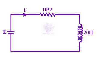
Determine the charge on the capacitor in the following circuit: 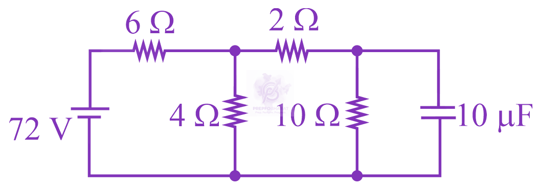
In free space, a particle $A$ of charge $1 \mu C$ is held fixed at point $P$ . Another particle $B$ of the same charge and mass $4 \mu g$ is kept at a distance of $1 mm$ from $P.$ If $B$ is released, then its velocity at a distance of $9 mm$ from $P$ is: [Take $\frac{1}{4\pi {\epsilon }_{0}}=9\times {10}^{9} N {m}^{2} {C}^{-2}$ ]
The figure shows a capacitor of capacitance $C$ connected to a battery via a switch, having a total charge $Q$ on it, in steady-state. When the switch $S$ is turned from position $A$ to position $B$, the energy dissipated in the circuit is 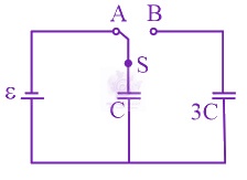
A wire of resistance $R$ is bent to form a square $ABCD$ as shown in the figure. The effective resistance between $E$ and $C$ is: ( $E$ is mid-point of arm $CD$ ) 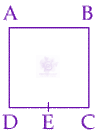
In the figure shown below, the charge on the left plate of the 10F capacitor is -30C. The charge on the right plate of the 6F capacitor is: 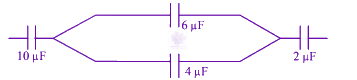
The actual value of resistance $R$ , shown in the figure is $30\Omega .$ This is measured in an experiment as shown using the standard formula $R=\frac{V}{I}$ , where $V$ and $I$ are the readings of the voltmeter and ammeter, respectively. If the measured value of $R$ is $5%$ less, then the internal resistance of the voltmeter is: 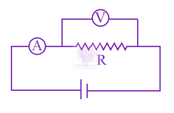
A coil of self inductance $10 mH$ and resistance of $0.1 \Omega$ is connected through a switch to a battery of internal resistance $0.9 \Omega$ . After the switch is closed, the time taken for the current to attain $80%$ of the saturation value is: $[ \mathrm{ln}5=1.6 ]$
In an experiment, the resistance of a material is plotted as a function of temperature (in some range). As shown in the figure, it is a straight line. 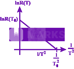 One may conclude that
Three charges $+Q, q,+Q$ are placed respectively, at distance, $0,d/2$ and $d$ from the origin, on the $x$ -axis. If the net force experienced by $+Q,$ placed at $x=0,$ is zero, then value of $q$ is:
The resistance of a galvanometer is $50 ohm$ and the maximum current which can be passed through it is $0.002 A.$ What resistance must be connected to it in order to convert it into an ammeter of range $0-0.5 A?$
The electric field in a region is given by $\vec{E}=(Ax+B) \hat{i} ,$ where $E$ is in $N{C}^{-1}$ and $x$ is in metres. The values of constants are $A=20 SI$ unit and $B=10 SI$ unit. If the potential at $x=1$ is ${V}_{1}$ and that at $x=-5$ is ${V}_{2},$ then ${V}_{1}-{V}_{2}$ is
A simple pendulum of length $L$ is placed between the plates of a parallel plate capacitor having electric field $E$ , as shown in figure. Its bob has mass $m$ and charge $q$ . The time period of the pendulum is given by: 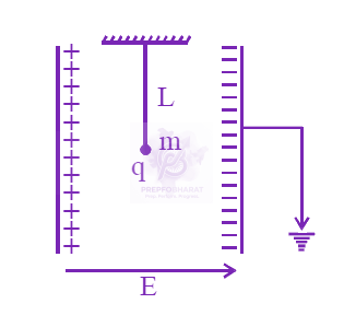
A particle having the same charge as of electron moves in a circular path of radius $0.5 cm$ under the influence of a magnetic field of $0.5 T.$ If an electric field of 100 V/m makes it to move in a straight path, then the mass of the particle is (Given charge of electron $=1.6\times {10}^{-19}C$ )
The parallel combination of two air filled parallel plate capacitors of capacitance $C$ and $nC$ is connected to a battery of voltage, $V.$ When the capacitors are fully charged, the battery is removed and after that a dielectric material of dielectric constant $K$ is placed the two plates of the first capacitor. The new potential difference of the combined system is:
A rigid square loop of side $‘a’$ and carrying current ${I}_{2}$ is lying on a horizontal surface near a long current ${I}_{1}$ carrying wire in the same plane as shown in figure. The net force on the loop due to the wire will be: 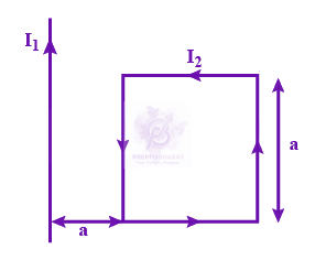
Let a total charge $2Q$ be distributed in a sphere of radius $R,$ with the charge density given by $\rho (r)=kr,$ where $r$ is the distance from the centre. Two charges $A$ and $B$ , of $-Q$ each, are placed on diametrically opposite points, at equal distance, a, from the centre. If $A$ and $B$ do not experience any force, then:
A galvanometer having a resistance of $20 \Omega$ and 30 division on both sides has figure of merit 0.005 ampere/ division. The resistance that should be connected in series such that it can be used as a voltmeter upto 15 volt, is:
Determine the electric dipole moment of the system of three charges, placed on the vertices of an equilateral triangle, as shown in the figure: 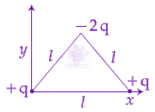
A power transmission line feeds input power at $2300 V$ to a step down transformer with its primary windings having $4000$ turns. The output power is delivered at $230 V$ by the transformer. If the current in the primary of the transformer is $5A$ and its efficiency is $90%$, the output current would be:
A conducting circular loop made of a thin wire has area $3.5\times {10}^{-2} {m}^{2}$ and resistance $10 \Omega$ It is placed perpendicular to a time-dependent magnetic field $B(t)=(0.4T)\mathrm{sin}(50\pi t)$ The field is uniform in space. Then the net charge flowing through the loop during $t=0 s$ and $t=10 \mathrm{ms}$ is close to
A square loop is carrying a steady current $I$ and the magnitude of its magnetic dipole moment is $m$ . If this square loop is changed to a circular loop and it carries the same current, the magnitude of the magnetic dipole moment of circular loop will be:
The magnitude of the magnetic field at the centre of an equilateral triangular loop of side $1 m$ which is carrying a current of $10 A$ is: [Take ${\mu }_{0}=4\pi \times {10}^{-7} N {A}^{-2}$ ]
A current loop, having two circular arcs joined by two radial lines is shown in the figure. It carries a current of $10 A.$ The magnetic field at point $O$ will be close to: 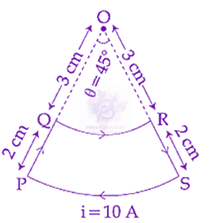
In the given circuit the cells have zero internal resistance. The currents (in amperes) passing through resistance ${R}_{1}$ and ${R}_{2}$ respectively, are: 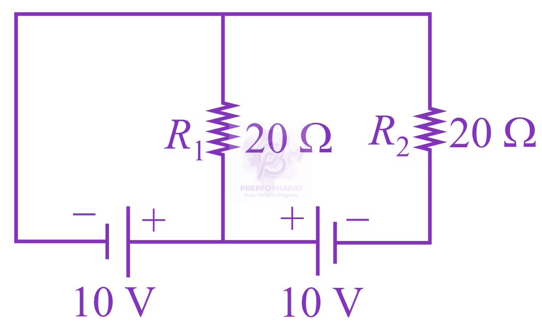
There is a uniform spherically symmetric surface charge density at a distance ${R}_{0}$ from the origin. The charge distribution is initially at rest and starts expanding because of mutual repulsion. The figure that represents best the speed $V(R(t))$ of the distribution as a function of its instantaneous radius $R(t)$ is:
A uniform metallic wire has a resistance of $18\Omega$ and is bent into an equilateral triangle. Then, the resistance between any two vertices of the triangle is:
A magnet of total magnetic moment ${10}^{-2}\hat{i} A{m}^{2}$ is placed in a time varying magnetic field, $B\hat{i}(\mathrm{cos}\omega t)$ where $B=1$ Tesla and $\omega =0.125 \mathrm{rad}{s}^{-1}$. The work done for reversing the direction of the magnetic moment at $t=1$ second, is:
Two very long, straight, and insulated wires are kept at ${90}^{o}$ angle from each other in $xy-plane$ as shown in figure. 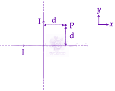 These wires carry currents of equal magnitude $I$ , whose direction are shown in the figure. The net magnetic field at point $P$ will be:
A plane electromagnetic wave of frequency $50 MHz$ travels in free space along the positive $x$ - direction. At a particular point in space and time, $\vec{E}=6.3 \hat{j} V/m,$ The corresponding magnetic field $\vec{B,}$ at that point will be:
If the magnetic field of a plane electromagnetic wave is given by (The speed of light $=3\times {10}^{8} m/s$) $B=100\times {10}^{-6}\mathrm{sin}[2\pi \times 2\times {10}^{15}(t-\frac{x}{c})]$ then the maximum electric field associated with it is:
Two wires $A$ & $B$ are carrying currents ${I}_{1}$ and ${I}_{2}$ as shown in the figure. The separation between them is $d$ . A third wire $C$ carrying a current $I$ is to be kept parallel to them at a distance $x$ from $A$ such that the net force acting on it is zero. The possible values of $x$ are: 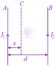
A thin ring of $10 cm$ radius carries a uniformly distributed charge. The ring rotates at a constant angular speed of $40\pi rad{s}^{-1}$ about its axis, perpendicular to its plane. Is the magnetic field its centre is $3.8\times {10}^{-9}T$ , then the charge carried by the ring is close to $({\mu }_{0}=4\pi \times {10}^{-7}N/{A}^{2}).$
An insulating thin rod of length $l$ has a linear charge density $\rho (x)={\rho }_{0}\frac{x}{l}$ on it. The rod is rotated about an axis passing through the origin $(x=0)$ and perpendicular to the rod. If the rod makes $n$ rotations per second, then the time averaged magnetic moment of the rod is:
A moving coil galvanometer allows a full scale current of ${10}^{-4} A$ . A series resistance of $2 \times {10}^{4} \Omega$ is required to convert the galvanometer into a voltmeter of range $0-5 V$ . Therefore, the value of shunt resistance required to convert the above galvanometer into an ammeter of range $0-10 mA$ is:
A Point dipole $\vec{p}=-{p}_{0}\hat{x}$ is kept at the origin. The potential and electric field due to this dipole on the $y-axis$ at a distance $d$ are, respectively: (Taken $V=0$ at infinity)
A uniformly charged ring of radius $3a$ and total charge $q$ is placed in $x‐y$ plane centred at origin. A point charge $q$ is moving towards the ring along the $z-$ axis and has speed $v$ at $z=4a$ . The minimum value of $v$ such that it crosses the origin is:
Four point charges $-q, +q, +q$ and $-q$ are placed on y-axis at $y=-2d, y=-d,$ and $y=+2d,$ respectively. The magnitude of the electric field $E$ at a point on the x-axis at $x=D,$ with $D\gg d,$ will behave as:
A charge $Q$ is distributed over three concentric spherical shells of radii $a, b, c (a<b<c)$ such that their surface charge densities are equal to one another. The total potential at a point at distance $r$ from their common centre, where $r<a,$ would be:
In a Wheatstone bridge (see fig.), Resistances $P$ and $Q$ are approximatelyequal. When $R=400 \Omega$, the bridge is balanced. On interchanging $\mathrm{P}$ and $\mathrm{Q}$, the value of $\mathrm{R},$ for balance, is $405 \Omega$. The value of $Y$ is close to 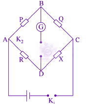
Seven capacitors, each of capacitance $2 \mu \mathrm{F},$ are to be connected in a configuration to obtain an effective capacitance of $\left(\frac{6}{13}\right) \mu \mathrm{F} .$ Which of the combinations, shown in figures below, will achieve the desired value?
A cell of internal resistance $r$ drives current through an external resistance $R.$ The power delivered by the cell to the external resistance will be maximum when:
A capacitor with capacitance $5 \mu F$ is charged to $5 \mu C$ . If the plates are pulled apart to reduce the capacitance to $2 \mu F$, how much work is done?
Two magnetic dipoles $X$ and $Y$ are placed at a separation $d$ , with their axes perpendicular to each other. The dipole moment of $Y$ is twice that of $X$ . A particle of charge $q$ is passing through their mid-point $P$ , at angle $\theta ={45}^{o}$ with the horizontal line, as shown in figure. What would be the magnitude of force on the particle at that instant? ( $d$ is much larger than the dimension of the dipole) 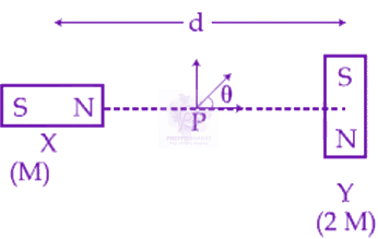
In the given circuit diagram, the currents, ${I}_{1}=-0.3 A, {I}_{4}=0.8 A$ and ${I}_{5}=0.4 A,$ are flowing as shown. The currents ${I}_{2}, {I}_{3}$ and ${I}_{6},$ respectively, are: 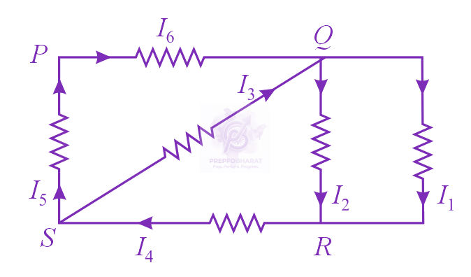
Space between two concentric conducting spheres of radii $a$ and $b$ $(b>a)$ is filled with a medium of resistivity $\rho$ . The resistance between the two spheres will be:
In the given circuit, an ideal voltmeter connected across the $10 \Omega$ resistance reads $2 V$ . The internal resistance $r$ , of each cell is: 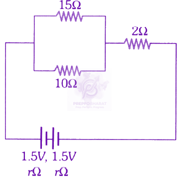
A metal wire of resistance $3 \Omega$ is elongated to make a uniform wire of double its previous length. This new wire is now bent and the ends joined to make a circle. If two points on this circle make an angle ${60}^{o}$ at the center, the equivalent resistance between these two points will be:
Two electric bulbs, rated at $(25 W, 220V)$ and $(100 W, 220V),$ are connected in series across a $220\text{V}$ voltage source. If the $25 W$ and $100 W$ bulbs draw powers ${P}_{1}$ and ${P}_{2}$ respectively, then:
In the circuit shown, the potential difference between $\mathrm{A}$ and $B$ is 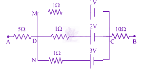
A paramagnetic material has ${10}^{28}\mathrm{atoms}{m}^{-3}$. Its magnetic susceptibility at temperature $350 K$ is $2.8×{10}^{-4}$. Its susceptibility at $300 K$ is
A series $AC$ circuit containing an inductor $(20 \mathrm{mH}),$ a capacitor $(120\text{ μ}F)$ and a resistor $(60 \Omega )$ is driven by an $AC$ source of $24 V/50 \mathrm{Hz}.$ The energy dissipated in the circuit in $60 s$ is:
A system of three charges are placed as shown in the figure: 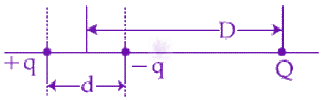 If $D >> d,$ the potential energy of the system is best given by:
A parallel plate capacitor has $1\mu F$ capacitance. One of its two plates is given $+2\mu C$ charge and the other plate, $+4 \mu C$ charge. The potential difference developed across the capacitor is:
The galvanometer deflection, when key ${K}_{1}$ is closed but ${K}_{2}$ is open, equals ${\theta }_{0}$ (see figure). On closing ${K}_{2}$ also and adjusting ${R}_{2}$ to $5\Omega ,$ the deflection in galvanometer becomes $\frac{{\theta }_{0}}{5}.$ The resistance of the galvanometer is, then, given by [Neglect the internal resistance of battery]: 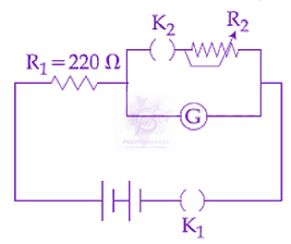
Two point charges ${q}_{1}(\sqrt{10} \mu C)$ and ${q}_{2}(-25 \mu C)$ are placed on the $x$ -axis at $x=1 m$ and $x=4 m$ respectively. The electric field $(\text{in} V/m)$ at a point $y=3 m$ on $y$-axis is, $[\text{Take}\frac{1}{4\pi {\epsilon }_{0}}=9\times {10}^{9} N{m}^{2}{C}^{-2}]$
In the given circuit the internal resistance of the $18V$ cell is negligible. If ${R}_{1}=400 \Omega , {R}_{3}=100 \Omega$ and ${R}_{4}=500 \Omega$ and the reading of an ideal voltmeter across ${R}_{4}$ is $5 V,$ then the value of ${R}_{2}$ will be: 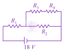
Two identical parallel plate capacitors, of capacitance $C$ each, have plates of area $A,$ separated by a distance $d$ . The space between the plates of the two capacitors, is filled with three dielectrics, of equal thickness and dielectric constants ${K}_{1}, {K}_{2}$ and ${K}_{3}$ . The first capaciitor is filled as shown in figure $I,$ and the second one is filled as shown in figure $II.$ If these two modified capacitors are charged by the same potential $V$ , the ratio of the energy stored in the two, would be $({E}_{1}$ refers to capacitor $(I)$ and ${E}_{2}$ to capacitor $(II)$ ): 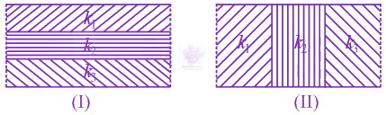
A current of $2 \mathrm{mA}$ was passed through an unknown resistor which dissipated a power of $4.4 W.$ Dissipated power when an ideal power supply of $11 V$ is connected across it is:
Two coils $'P'$ and $'Q'$ are separated by some distance. When a current of $3 A$ flows through coil $'{P}^{'},$ a magnetic flux of ${10}^{-3} Wb$ passes through $'{Q}^{'}.$ No current is passed through $'{Q}^{'}.$ When no current passes through $'P'$ and a current of $2 A$ passes through $'{Q}^{'},$ the flux through $'P'$ is:
Two equal resistances when connected in series to a battery, consume electric power of $60 \mathrm{~W}$. If these resistance are now connected in parallel combination to the same battery, the electric power consumed will be :
A very long solenoid of radius $R$ is carrying current $I(t)=kt{e}^{-\alpha t}(k>0),$ as a function of time $(t\geq 0).$ Counterclockwise current is taken to be positive. A circular conducting coil of radius $2R$ is placed in the equitorial plane of the solenoid and concentric with the solenoid. The current induced in the outer coil is correctly depicted, as a function of time, by:
Charge is distributed within a sphere of radius $R$ with a volume charge density $\rho (r)=\frac{A}{{r}^{2}}{e}^{-\frac{2r}{a}},$ where $A$ and $a$ are constants. If $Q$ is the total charge of this charge distribution, the radius $R$ is:
The given graph shows variation (with distancer from centre) of: 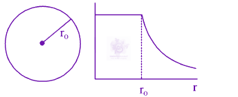
A parallel plate capacitor with square plates is filled with four dielectrics of dielectric constants ${K}_{1}, {K}_{2}, {K}_{3}, {K}_{4}$ arranged as shown in the figure. The effective dielectric constant $K$ will be: 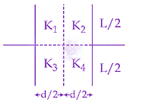
Mobility of electrons in a semiconductor is defined as the ratio of their drift velocity to the applied electric field. If, for an $\text{N}$-type semiconductor, the density of electrons is ${10}^{19} {m}^{-3}$ and their mobility is $1.6 {m}^{2}{V}^{-1}{s}^{-1}$, then the resistivity of the semiconductor (since it is an $\text{N}$-type semiconductor contribution of holes is ignored) is close to:
A parallel plate capacitor having capacitance $12 \mathrm{pF}$ is charged by a battery to a potential difference of $10 V$ between its plates. The charging battery is now disconnected and a porcelain slab of dielectric constant $6.5$ is slipped between the plates. The work done by the capacitor on the slab is
A moving coil galvanometer has a coil with $175$ turns and area $1 c{m}^{2}.$ It uses a torsion band of torsion constant ${10}^{-6} Nm/rad$ The coil is placed in a magnetic field B parallel to its plane. The coil deflects by ${1}^{o}$ for a current of $1 mA$ The value of B (in tesla) is approximately:
The self induced emf of a coil is $25$ volts. When the current in it is changed at uniform rate from $10A$ to $25A$ in $1s$ , the change in the energy of the inductance is:
As shown in the figure, two infinitely long, identical wires are bent by ${90}^{o}$ and placed in such a way that the segments $LP$ and $QM$ are along the $x$ - axis, while segments $PS$ and $QN$ are parallel to the $y$ - axis. If $OP=OQ=4cm,$ and the magnitude of the magnetic field at $O$ is ${10}^{-4} T,$ and the two wires carry equal currents (see figure), the magnitude of the current in each wire and the direction of the magnetic field at $O$ will be $({\mu }_{0}=4\pi \times {10}^{-7}N{A}^{-2}):$ 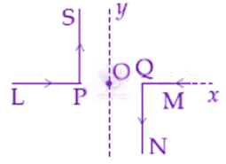
A moving coil galvanometer, having a resistance $G,$ produces full scale deflection when a current ${I}_{G}$ flows through it. This galvanometer can be converted into (i) an ammeter of range 0 to ${I}_{o}({I}_{0}>{I}_{g})$ by connecting a shunt resistance ${R}_{A}$ to it and (ii) into a voltmeter of range 0 to $V(V=G{I}_{0})$ by connecting a series resistance ${R}_{V}$ to it. Then,
The figure shows a square loop $L$ of side $5 cm$ which is connected to a network of resistances. The whole setup is moving towards the right with a constant speed of $1cm{s}^{-1}$ . At some instant, a part of $L$ is in a uniform magnetic field of $1T$ perpendicular to the plane of the loop. If the resistance of $L$ is $1.7 \Omega ,$ the current in the loop at that instant will be close to: 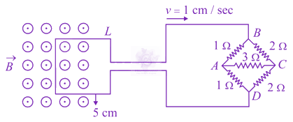
Four equal point charges $Q$ each are placed in the $xy$ plane at $(0, 2),(4, 2),(4, -2)$ and $(0, -2)$ . The work required to put a fifth charge $Q$ at the origin of the coordinate system will be:
To verify Ohm’s law, a student connects the voltmeter across the battery as shown in the figure. The measured voltage is plotted as a function of the current, and the following graph is obtained: 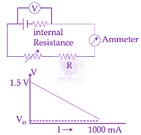 If ${V}_{o}$ is almost zero, identify the correct statement:
A proton and an $\alpha$- particle (with their masses in the ratio of $1:4$ and charges in the ratio of $1:2$ ) are accelerated from rest through a potential difference $V.$ If a uniform magnetic field $(B)$ is set up perpendicular to their velocities, the ratio of the radii ${r}_{p}:{r}_{\alpha }$ of the circular paths described by them will be:
A galvanometer of resistance $100 \Omega$ has $50$ divisions on its scale and has sensitivity of $20\mu A/ division$ . It is to be converted to voltmeter with three ranges, of $0-2 V,0-10 V$ and $0-20 V.$ The appropriate circuit to do so is:
The bob of a simple pendulum has mass $2 g$ and a charge of $5.0 \mu C.$ It is at rest in a uniform horizontal electric field of intensity $2000 V/m$ At equilibrium, the angle that the pendulum makes with the vertical is: $(takeg=10 m/{s}^{2})$
Charges $-q$ and $+q$, located at $A$ and $B$, respectively, constitute an electric dipole. Distance $AB=2a$, $O$ is the mid point of the dipole and $OP$ is perpendicular to $AB$. A charge $Q$ is placed at $P$ where $OP=y$ and $y\gg 2a$. The charge $Q$ experiences an electrostatic force $F$. If $Q$ is now moved along the equatorial line to $P'$ such that $OP'=(\frac{y}{3})$ the force on $Q$ will be close to$(\frac{y}{3}\ll 2a)$ 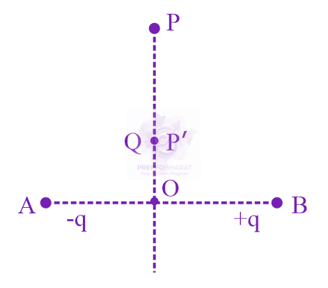
A current of $5 A$ passes through a copper conductor (resistivity $=1.7\times {10}^{-8} \Omega m$ ) of radius of cross-section $5 mm$ . Find the mobility of the charges if their drift velocity is $1.1\times {10}^{-3} {\mathrm{ms}}^{-1}$ .
In the circuit shown, find $C$ if the effective capacitance of the whole circuit is to be $0.5 \mu F.$ All values in the circuit are in $\mu F.$ 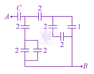
Shown in the figure is a shell made of a conductor. It has inner radius $a$ and outer radius $b$, and carries charge $Q$ . At its centre a dipole $\vec{p}$ is placed as shown then: 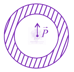
The total number of turns and cross-section area in a solenoid is fixed. However, its length $L$ is varied by adjusting the separation between windings. The inductance of solenoid will be proportional to:
For a uniformly charged ring of radius $R,$ the electric field on its axis has the largest magnitude at a distance $h$ from its centre. Then value of $h$ is:
Voltage rating of a parallel plate capacitor is $500 V.$ Its dielectric can withstand a maximum electric field of ${10}^{6}V/m.$ The plate area is ${10}^{-4} {m}^{2}$ . What is the dielectric constant if the capacitance is $15 pF$ ? $(given{\epsilon }_{0}=8.86\times {10}^{-12}{C}^{2}/N{m}^{2})$
The region between $y=0$ and $y=\mathrm{d}$ contains a magnetic field $\overrightarrow{\mathrm{B}}=\mathrm{B} \hat{\mathrm{z}}$. A particle of mass $\mathrm{m}$ and charge $\mathrm{q}$ enters the region with a velocity $\vec{v}=v \hat{i} .$ if $\mathrm{d}=\frac{\mathrm{m} v}{2 \mathrm{qB}},$ the acceleration of the charged particle at the point of its emergence at the other side is :
A solid metal cube of edge length $2 \mathrm{cm}$ is moving in the positive $y$-direction, at a constant speed of $6 m{s}^{-1}$. There is a uniform magnetic field of $\text{0.1} T$ in the positive $z$-direction. The potential difference between the two faces of the cube, perpendicular to the $x$-axis, is
A $10 m$ long horizontal wire extends from North East to South West. It is falling with a speed of $5.0 m{s}^{-1},$ at right angles to the horizontal component of the earth's magnetic field of $0.3\times {10}^{-4}\mathrm{Wb}{m}^{-2}.$ The value of the induced emf in the wire is:
A galvanometer, whose resistance is $50 \mathrm{ohm}$ , has $25$ divisions in it. When a current of $4\times {10}^{-4}$ A passes through it, its needle (pointer) deflects by one division. To use this galvanometer as a voltmeter of range $2.5 V$ it should be connected to a resistance of:
Three charges $Q,+y$ and $+q$ are placed at the vertices of a right-angle isosceles triangle as shown below. The net electrostatic energy of the configuration is zero, if the value of $\mathrm{Q}$ is 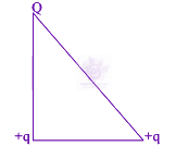
The mean intensity of radiation on the surface of the Sun is about ${10}^{8}W/{m}^{2}.$ The rms value of the corresponding magnetic field is closest to:
Sunlight of intensity $50 W{m}^{-2}$is incident normally on the surface of a solar panel. Some part of incident energy ($25%$) is reflected from the surface and the rest is absorbed. The force exerted on $1 {m}^{2}$ surface area will be close to $(c=3\times {10}^{8}m{s}^{-1})$
Given below in the left column are different modes of communication using the kinds of waves given in the right column. <table class="pyq-table"><tbody><tr><th>(1) Optical Fibre Communication</th><th>(P) Ultrasound</th></tr><tr><td>(2) Radar</td><td>(Q) Infrared Light</td></tr><tr><td>(3) Sonar</td><td>(R) Microwaves</td></tr><tr><td>(4) Mobile Phones</td><td>(S) Radio Waves</td></tr></tbody></table> From the options given below, find the most appropriate match between entries in the left and the right column.
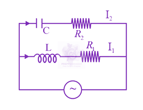 In the above circuit, $C=\frac{ \sqrt{ 3 } }{2} \mu F, {R}_{2} =20 \Omega , L=\frac{ \sqrt{ 3 } }{ 10} H$ and ${R}_{1} =10 \Omega .$ Current in $L\text{-}{R}_{1}$ path is ${I}_{1}$ and in $C-{R}_{2}$ path it is ${I}_{2} .$ The voltage of AC source is given by, V=200 2 sin( 100 t ) volts. The phase difference between ${I}_{1}$ and ${I}_{2}$ is:
An infinitely long current carrying wire and a small current carrying loop are in the plane of the paper as shown. The radius of the loop is $a$ and distance of its centre from the wire is $d (d\gg a).$ If the loop applies a force $F$ on the wire then: 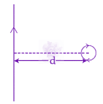
A particle of mass $m$ and charge $q$ is in an electric and magnetic field given by $$ \overrightarrow{\mathrm{E}}=2 \hat{i}+3 \hat{j} ; \overrightarrow{\mathrm{B}}=4 \hat{j}+6 \hat{k} $$ The charged particle is shifted from the origin to the point $\mathrm{P}(x=1 ; y=1)$ along a straight path. The magnitude of the total work done is :
An electron, moving along the $x-$ axis with an initial energy of $100 eV,$ enters a region of magnetic field $\vec{B}=(1.5\times {10}^{-3} T)\hat{k}$ at S (see figure). The field extends between $x=0$ and $x=2 cm.$ The electron is detected at the point $Q$ on a screen placed $8 cm$ away from the point $S.$ The distance d between $P$ and $Q$ (on the screen) is: (electron’s charge $1.6\times {10}^{-19} C$ , mass of electron $=9.1\times {10}^{-31} kg$ ) 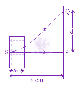
Figure shows charge $(q)$ versus voltage $(V)$ graph for series and parallel combination of two given capacitors. The capacitances are: 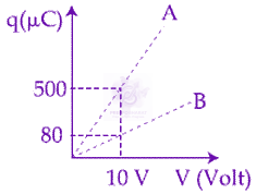
The resistive network shown below is connected to a $D.C.$ source of $16 V.$ The power consumed by the network is $4$ Watt. The value of $R$ is: 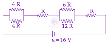
In the circuit shown, 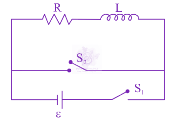 the switch $S_{1}$ is closed at time $t=0$ and the switch $S_{2}$ is kept open. At some later time $\left(\mathrm{t}_{0}\right)$, the switch $\mathrm{S}_{1}$ is opened and $\mathrm{S}_{2}$ is closed. the behaviour of the current I as a function of time ' $\mathrm{t}$ ' is given by:
A rectangular coil (Dimension $5 cm \times 2.5 cm$ ) with $100$ turns, carrying a current of $3 A$ in the clock-wise direction, is kept centered at the origin and in the $X-Z$ plane. A magnetic field of $1 T$ is applied along $X-axis$ . If the coil is tilted through $45^{\circ}$ about $Z-axis$ , then the torque on the coil is:
In the given circuit, the charge on $4 \mu F$ capacitor will be: 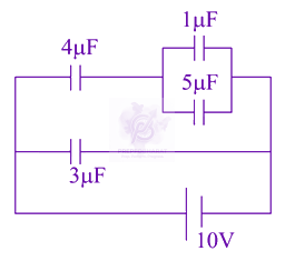
The charge on a capacitor plate in a circuit, as a function of time, is shown in the figure: 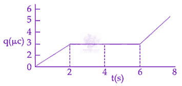 What is the value of current at $t=4 s?$
Two electric dipoles, $A,$ $B$ with respective dipole moments $\vec{{d}_{A}}=-4qa\hat{i}$ and $\vec{{d}_{B}}=-2qa\hat{i}$ are placed on the $x$ -axis with a separation $R,$ as shown in the figure 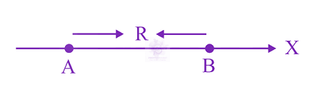 The distance from $A$ at which both of them produce the same potential is:
An electromagnetic wave of intensity $50 \mathrm{Wm}^{-2}$ enters in a medium of refractive index 'n' without any loss. The ratio of the magnitudes of electric fields, and the ratio of the magnitudes of magnetic fields of the wave before and after entering into the medium are respectively, given by :
A parallel plate capacitor with plates of area $1 {m}^{2}$ each, are at a separation of $0.1 m.$ If the electric field between the plates is $100 N/C,$ the magnitude of charge on each plate is: $( \text{Take} {\in }_{0} =8.85\times { 10}^{ -12} \frac{ {C}^{2} }{ N\text{-}{m}^{2} } )$
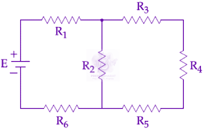
In the figure shown, what is the current (in Ampere) drawn from the battery? You are given: ${R}_{1}=15 \Omega , {R}_{2}=10 \Omega , {R}_{3}=20 \Omega , {R}_{4}=5 \Omega , {R}_{5}=25 \Omega , {R}_{6}=30 \Omega , E=15V$