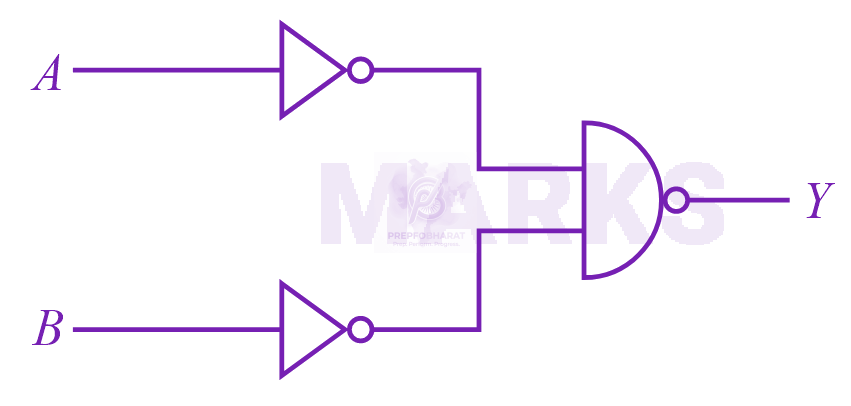
The output of the given circuit can be depicted schematically as follows:
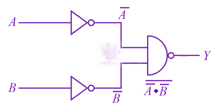
Hence. from the above diagram, the output can be written as
Y===A⋅BA+BA+B
Thus, the given circuit represents an OR logic, the truth table for which is given below:
| A | B | Y |
| 0 | 0 | 0 |
| 0 | 1 | 1 |
| 1 | 0 | 1 |
| 1 | 1 | 1 |