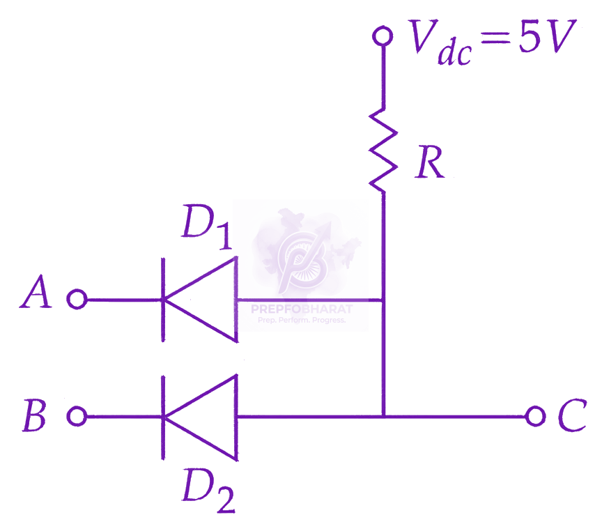
If A=0 and B=0: Both diodes are forward biased. The potential at C is pulled down to approximately 0V (logic 0).
If A=0 and B=1: Diode D1 is forward biased, pulling the potential at C down to 0V (logic 0). Diode D2 is reverse biased.
If A=1 and B=0: Diode D2 is forward biased, pulling the potential at C down to 0V (logic 0). Diode D1 is reverse biased.
If A=1 and B=1: Both diodes are reverse biased. No current flows through the resistor R, so the potential at C remains at Vdc=5V (logic 1).
The truth table is:
| A | B | C |
|---|---|---|
| 0 | 0 | 0 |
| 0 | 1 | 0 |
| 1 | 0 | 0 |
| 1 | 1 | 1 |
This truth table corresponds to the AND gate logic operation C=A⋅B.
Therefore, the circuit functions as an AND gate.