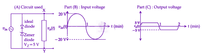




From the output waveform, the input sinusoid oscillating between +20 V and −20 V is being clipped at +5 V during the positive half-cycle and at −5 V during the negative half-cycle.
Analysis of the existing branch:
The given parallel branch has an ideal diode and a Zener diode (VZ=5 V) connected cathode-to-cathode.
During the positive half-cycle (vin>0), node X is positive with respect to node Y. The ideal diode becomes forward-biased and the Zener diode enters reverse breakdown, clamping the output at +5 V. This branch handles the positive clipping.
During the negative half-cycle (vin<0), the ideal diode in this branch is reverse-biased, so the branch acts as an open circuit and cannot produce the negative clipping seen in the output.
Requirement for the unknown box:
The component in the box must clamp the output at −5 V during the negative half-cycle, i.e., it must conduct when Y is 5 V more positive than X.
For a sharp 5 V clipping level, we need a Zener diode (for the 5 V drop) together with an ideal diode (to block conduction in the opposite direction). Resistors cannot produce the flat clipping shown, so options with resistors are ruled out.
Polarity of the connection:
For current to flow from Y to X with a 5 V drop:
The Zener must be reverse-biased, so current from Y must enter its cathode ⇒ Zener's cathode faces Y.
The ideal diode must be forward-biased, so current must exit through its cathode towards X ⇒ ideal diode's cathode faces X.
Hence, the two diodes must be connected anode-to-anode.
Evaluating the options:
Options (1) and (3) contain resistors and cannot give sharp clipping.
Option (2) is a cathode-to-cathode configuration, which would again clip at +5 V (redundant).
Option (4) has the ideal diode's cathode at X and the Zener's cathode at Y, meeting anode-to-anode in the middle. When VY>VX, current flows from Y through the Zener (reverse breakdown, 5 V drop) and through the ideal diode (forward-biased, 0 V drop) to X, clamping vo(t) at −5 V.
Hence, the correct option is (4).