JEE Main Physics — Electromagnetism previous year questions with solutions.
In the experiment of calibration of voltmeter, a standard cell of e.m.f. $1.1$ volt is balanced against $440 \mathrm{~cm}$ of potential wire. The potential difference across the ends of resistance is found to balance against $220 \mathrm{~cm}$ of the wire. The corresponding reading of voltmeter is $0.5$ volt. The error in the reading of volmeter will be:
The gap between the plates of a parallel plate capacitor of area $A$ and distance between plates $d$, is filled with a dielectric whose relative permittivity varies linearly from ${\epsilon }_{1}$ at one plate to ${\epsilon }_{2}$ at the other. The capacitance of the capacitor is
An example of a perfect diamagnet is a superconductor. This implies that when a superconductor is put in a magnetic field of intensity $B$, the magnetic field ${B}_{s}$ inside the superconductor will be such that
Three straight parallel current carrying conductors are shown in the figure. The force experienced by the middle conductor of length $25 \mathrm{~cm}$ is: 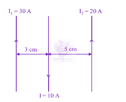
A lamp emits monochromatic green light uniformly in all directions. The lamp is $3 \%$ efficient in converting electrical power to electromagnetic waves and consumes $100 \mathrm{~W}$ of power. The amplitude of the electric field associated with the electromagnetic radiation at a distance of $5 \mathrm{~m}$ from the lamp will be nearly:
An electromagnetic wave of frequency $1 \times 10^{14}$ hertz is propagating along $\mathrm{z}$-axis. The amplitude of electric field is $4 \mathrm{~V} / \mathrm{m}$. If $\varepsilon_0=8.8 \times 10^{-12} \mathrm{C}^2 / \mathrm{N}-$ $\mathrm{m}^2$, then average energy density of electric field will be:
During the propagation of electromagnetic wave in a particular medium :-
Consider two thin identical conducting wires covered with very thin insulating material. One of the wires is bent into a loop and produces magnetic field $\mathrm{B}_1$, at its centre when a current $\mathrm{I}$ passes through it. The ratio $\mathrm{B}_1: \mathrm{B}_2$ is:
In the circuit diagrams (A, B, C and D) shown below, $\mathrm{R}$ is a high resistance and $\mathrm{S}$ is a resistance of the order of galvanometer resistance G. The correct circuit, corresponding to the half deflection method for finding the resistance and figure of merit of the galvanometer, is the circuit labelled as: (a) 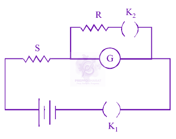 (b) (C)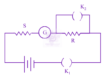 (d)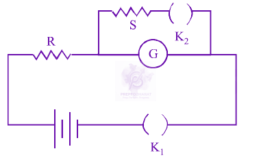
Three capacitances, each of 3 $\mu \text{F}$, are provided. These cannot be combined to provide the resultant capacitance of :
In a large building, there are 15 bulbs of 40 W, 5 bulbs of 100 W, 5 fans of 80 W and 1 heater of 1 kW. The voltage of the electric mains is 220 V. The minimum capacity of the main fuse of the building will be:
A cone of base radius $R$ and height $h$ is located in a uniform electric field $\overrightarrow{\mathrm{E}}$ parallel to its base. The electric flux entering the cone is:
The space between the plates of a parallel plate capacitor is filled with a 'dielectric' whose 'dielectric constant' varies with distance as per the relation: $$ \mathrm{K}(\mathrm{x})=\mathrm{K}_{\mathrm{o}}+\lambda \mathrm{x}(\lambda=\mathrm{a} \text { constant }) $$ The capacitance $\mathrm{C}$, of the capacitor, would be related to its vacuum capacitance $\mathrm{C}_{\mathrm{o}}$ for the relation :
A parallel plate capacitor is made of two circular plates separated by a distance of 5 mm and with a dielectric of dielectric constant 2.2 between them. When the electric field in the dielectric is $3 \times 1 {0}^{4} \text{ V/m}$, the charge density of the positive plate will be close to :
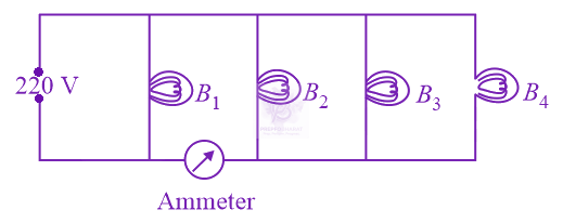 Four bulbs ${B}_{1}$, ${B}_{2}$, ${B}_{3}$ and ${B}_{4}$ of $100W$ each are connected to $220V$ main as shown in the figure. The reading in an ideal ammeter will be
Three identical bars A, B and C are made of different magnetic materials. When kept in a uniform magnetic field, the field lines around them look as follows: 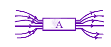 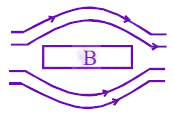 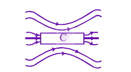 Make the correspondence of these bars with their material being diamagnetic ( $\mathrm{D})$, ferromagnetic (F) and paramagnetic $(\mathrm{P})$ :
When the rms voltages ${V}_{L} , {V}_{C}$ and ${V}_{R}$ are measured respectively across the inductor $L,$ the capacitor $C$ and the resistor $R$ in a series $LCR$ circuit connected to an $AC$ source, it is found that the ratio ${V}_{L} :{V}_{C} :{V}_{R} =1:2:3.$ If the rms voltage of the $AC$ source is $100 V,$ then ${V}_{R}$ is close to :
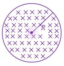 The figure shows a circular area of tthe radius $R$ where a uniform magnetic field $\vec{B}$ is going into the plane of the paper and increasing in magnitude at a constant rate. In that case, which of the following graphs, drawn schematically, correctly shows the variation of the induced electric field $E(r)$?
The circuit shown here has two batteries of $8.0 \mathrm{~V}$ and $16.0 \mathrm{~V}$ and three resistors $3 \Omega, 9 \Omega$ and $9 \Omega$ and a capacitor of $5.0 \mu \mathrm{F}$. 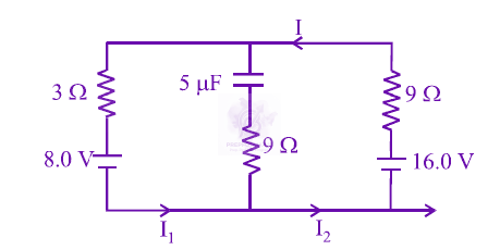 How much is the current $\mathrm{I}$ in the circuit in steady state?
A sinusoidal voltage $\mathrm{V}(\mathrm{t})=100 \sin (500 \mathrm{t})$ is applied across a pure inductance of $L=0.02 \mathrm{H}$. The current through the coil is:
The mid points of two small magnetic dipoles of length $d$ in end-on positions, are separated by a distance $x$$(x\gg d)$. The magnitude of force between them is proportional to ${x}^{-n}$ where $n$ is : 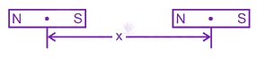
A square frame of side $10\mathrm{cm}$ and a long straight wire carrying current $1A$ are in the plane of the paper. Starting from close to the wire, the frame moves towards the right with a constant speed of $10m{s}^{-1}$ (see figure). The e.m.f induced at the time the left arm of the frame is at $x=10\mathrm{cm}$ from the wire is 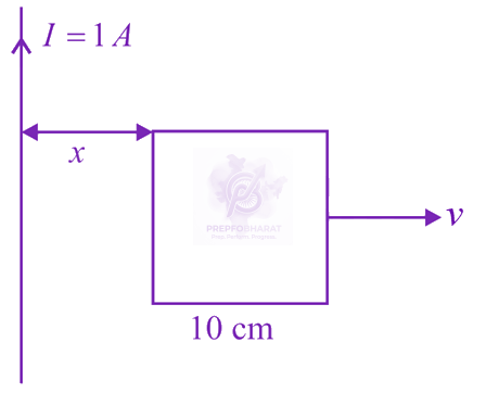
A d.c. main supply of e.m.f. $220V$ is connected across a storage battery of e.m.f. $200V$ through a resistance of $1 \Omega$. The battery terminals are connected to external resistance $R$. The minimum value of $R$, so that a current passes through the battery to charge it is:
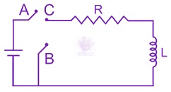
In the circuit shown here, the point '$C$' is kept connected to point $A$ '' till the current flowing through the circuit becomes constant. Afterward, suddenly, point '$C$' is disconnected from point $A$ '' and connected to point '$B$' at time $t=0$. Ratio of the voltage across resistance and the inductor at $t=\frac{L}{R}$ will be equal to :