JEE Main Physics — Electromagnetism previous year questions with solutions.
The region between two concentric spheres of radii 'a' and 'b', respectively (see figure), has volume charge density $\rho =\frac{A}{r}$ , where A is a constant and r is the distance from the centre. At the centre of the spheres is a point charge Q. The value of A such that the electric field in the region between the spheres will be constant, is: 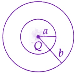
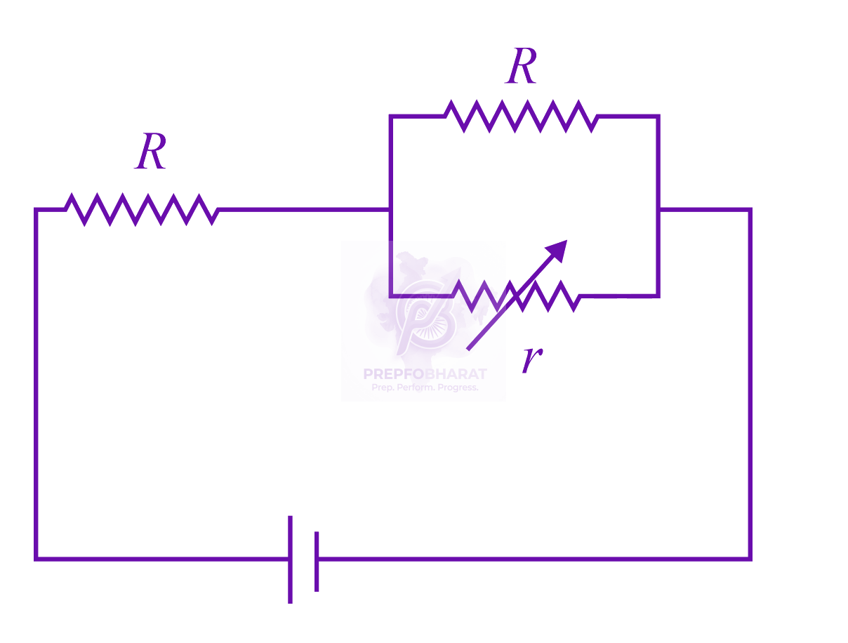 In the circuit shown, the resistance r is a variable resistance. If for $r=fR$ , the heat generation in r is maximum then the value of $f$ is
A conducting metal circular-wire-loop of radius $r$ is placed perpendicular to a magnetic field which varies with time as $B={B}_{0}{e}^{-\frac{t}{\tau }},$ where ${B}_{0} \mathrm{and} \tau$ are constants at time $t=0$. If the resistance of the loop is $R$, then the heat generated in the loop after a long time $(t\rightarrow \infty )$ is
A combination of capacitors is set up as shown in the figure. The magnitude of the electric field, due to a point charge Q (having a charge equal to the sum of the charges on the $4 \mu F$ and $9 \mu F$ capacitors), at a point distant 30 m from it, would equal: 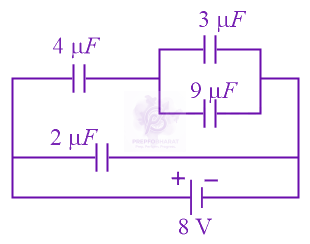
Within a spherical charge distribution of charge density $\rho (r),$ N equipotential surfaces of potential ${V}_{0}, {V}_{0}+\Delta V, {V}_{0}+2\Delta V,\ldots {V}_{0}+N\Delta V (\Delta V>0),$ are drawn and have increasing radii ${r}_{0}, {r}_{1}, {r}_{2},\ldots {r}_{N},$ respectively. If the difference in the radii of the surfaces is constant for all values of ${V}_{0} and \Delta V$ then :
Three capacitors each of $4 \mu F$ are to be connected in such a way that the effective capacitance is $6 \mu F$. This can be done by connecting them
A $50 \Omega$ resistance is connected to a battery of $5V$. A galvanometer of resistance $100 \Omega$ is to be used as an ammeter to measure current through the resistance, for this a resistance ${r}_{S}$ is connected to the galvanometer. Which of the following connections should be employed if the measured current is with in $1%$ of the current without the ammeter in the circuit?
Two coaxial solenoids of different radii carry current $I$ in the same direction. Let $\vec{{F}_{1}}$ be the magnetic force on the inner solenoid due to the outer one and $\vec{{F}_{2}}$ be the magnetic force on the outer solenoid due to the inner one. Then:
In the given circuits $(a)$ and $(b)$, switches ${\text{S}}_{1}$ and ${\text{S}}_{2}$ are closed at $\text{t}=0$ and kept close for a long time. The variation of currents in the two circuits for $\text{t}\geq 0$ are shown in the options. (Figures are schematic and not drawn to scale.) 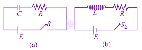
For the LCR circuit, shown here, the current is observed to lead the applied voltage. An additional capacitor ${C}^{'}$ , when joined with the capacitor C present in the circuit, makes the power factor of the circuit unity. The capacitor ${C}^{'}$ , must have been connected in: 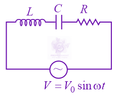
The AC voltage across a resistance can be measured using a:
A red $LED$ emits light at $0.1\mathrm{watt}$ uniformly around it. The amplitude of the electric field of the light at a distance of $1m$ from the diode is:
An inductor $( L=0.03 \text{H} )$ and a resistor $(R=0.15 \text{kΩ})$ are connected in series to a battery of $15 \text{V}$ E.M.F. in a circuit shown below. The key ${K}_{1}$ has been kept closed for a long time. Then at $t=0$, ${K}_{1}$ is opened and key ${K}_{2}$ is closed simultaneously. At $t=1 \text{ms}$ , the current in the circuit will be : $(\text{Take},{e}^{5}\approx 150)$ 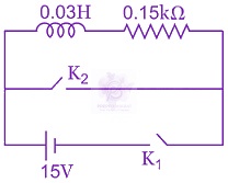
A rectangular loop of sides $10\mathrm{cm}$ and $5\mathrm{cm}$, carrying a current $I$ of $12A$, is placed in different orientations as shown in the figure below. (a) 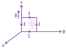 (b) 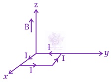 (c) 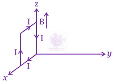 (d) 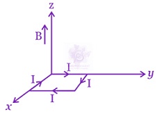 If there is a uniform magnetic field of $0.3T$ in the positive $z$ direction, in which orientations the loop would be in $(i)$ stable equilibrium and $(\mathrm{ii})$ unstable equilibrium?
An LCR circuit is equivalent to a damped pendulum. In an LCR circuit the capacitor is charged to ${Q}_{0}$ and then connected to the L and R as shown below: 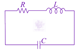 If a student plots graphs of the square of maximum charge $({Q}_{Max}^{2})$ on the capacitor with time (t) for two different values ${L}_{1}$ and ${L}_{2}({L}_{1}>{L}_{2})$ of L then which of the following represents this graph correctly? (plots are schematic and not drawn to scale)
A uniformly charged solid sphere of radius R has potential ${V}_{0}$ (measured with respect to $\infty$ ) on its surface. For this sphere the equipotential surfaces with potential $\frac{3{V}_{0}}{2},\frac{5{V}_{0}}{4},\frac{3{V}_{0}}{4}$ and $\frac{{V}_{0}}{4}$ have radius ${R}_{1}$ , ${R}_{2}, {R}_{3}$ and ${R}_{4}$ respectively. Then Note : This question had two option correct at the time of examination. Proper corrections are made in the question to avoid it.
In the figure is shown a system of four capacitors connected across a $10V$ battery. The charge that will flow from switch S when it is closed is: 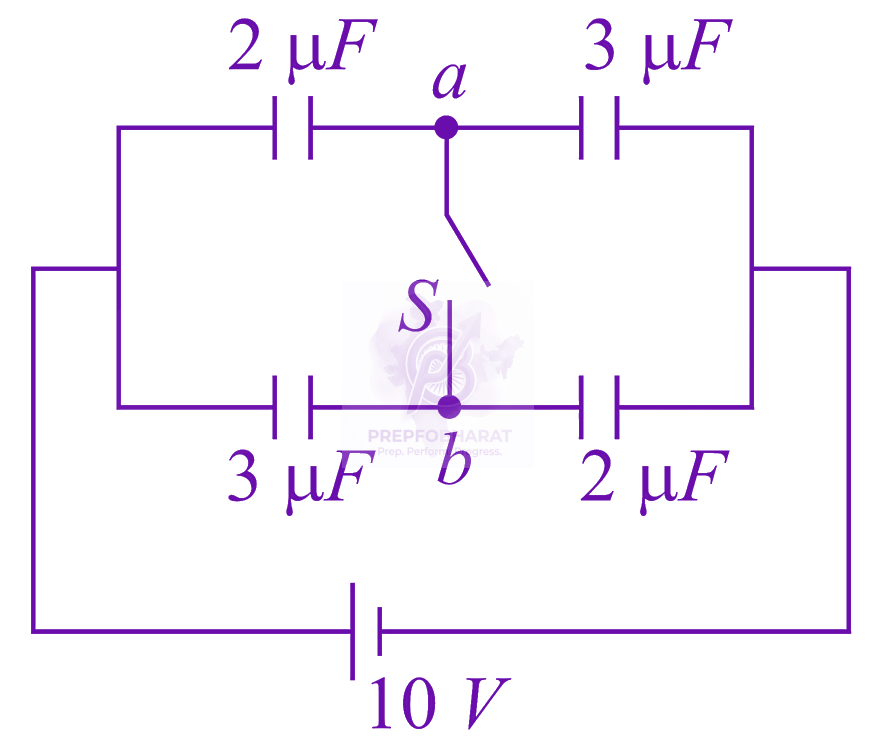
A wire carrying current $I$ is tied between points $P$ and $Q$ and is in the shape of a circular arc of radius $R$ due to a uniform magnetic field $B$ (perpendicular to the plane of the paper, as shown in the figure) in the vicinity of the wire. If the wire subtends an angle $2{\theta }_{o}$ at the center of the circle (of which it forms an arch) then the tension in the wire is: 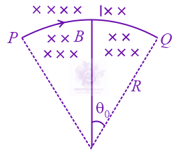
An electromagnetic wave travelling in the $x-$ direction has frequency of $2\times {10}^{14}Hz$ and electric field amplitude of $27V{m}^{–1}$ oscillates in $Y-$direction. From the options given below, which one describes the magnetic field for this wave?
A $25\mathrm{cm}$ long solenoid has the radius $2\mathrm{cm}$ and $500$ turns. It carries a current of $15A$. If it is equivalent to a magnet of the same size and magnetization $\vec{M} (\frac{Magnetic moment}{volume}),$then $|\vec{M}|$ is:
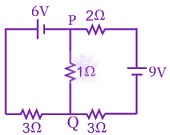 In the circuit shown, the current in the $1\Omega$ resistor is:
Shown in the figure are two point charges $+Q$ and $-Q$ inside the cavity of a spherical shell. The charges are kept near the surface of the cavity on opposite sides of the centre of the shell. If ${\sigma }_{1}$ is the surface charge on the inner surface and ${Q}_{1}$ net charge on it and ${\sigma }_{2}$ the surface charge on the outer surface and ${Q}_{2}$ net charge on it then: 
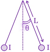 Two long currents carrying thin wires, both with current $I$, are held by insulating threads of length L and are in equilibrium as shown in the figure, with threads making an angle ' $\theta$ ' with the vertical. If wires have a mass $\lambda$ per unit length then the value of $I$ is: ($g=$ gravitational acceleration)
An electric field $\vec{E}=(25 \hat{i}+30 \hat{j})N{C}^{-1}$ exists in a region of space. If the potential at the origin is taken to be zero then the potential at $x=2m$, $y=2m$ is: