JEE Main Physics — Electromagnetism previous year questions with solutions.
The energy associated with electric field is $({U}_{E})$ and with magnetic field is $({U}_{B})$ for an electromagnetic wave in free space. Then:
The electric field of a plane polarized electromagnetic wave in free space at time $t=0$ is given by the expression $\vec{E}(x, y)=10\hat{j}cos(6x+8z)$. The magnetic field $\vec{B}(x, z, t)$ is given by ($c$ is the velocity of light.)
The electric field of a plane electromagnetic wave is given by $\vec{E}={E}_{0}\hat{i}\mathrm{cos}(kz)cos(\omega t)$ The corresponding magnetic field $\vec{B}$ is then given by:
The electric field in a region is given by $\vec{E}=(Ax+B) \hat{i} ,$ where $E$ is in $N{C}^{-1}$ and $x$ is in metres. The values of constants are $A=20 SI$ unit and $B=10 SI$ unit. If the potential at $x=1$ is ${V}_{1}$ and that at $x=-5$ is ${V}_{2},$ then ${V}_{1}-{V}_{2}$ is
The charge on a capacitor plate in a circuit, as a function of time, is shown in the figure: 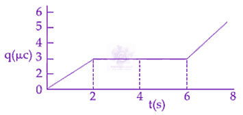 What is the value of current at $t=4 s?$
The bob of a simple pendulum has mass $2 g$ and a charge of $5.0 \mu C.$ It is at rest in a uniform horizontal electric field of intensity $2000 V/m$ At equilibrium, the angle that the pendulum makes with the vertical is: $(takeg=10 m/{s}^{2})$
The actual value of resistance $R$ , shown in the figure is $30\Omega .$ This is measured in an experiment as shown using the standard formula $R=\frac{V}{I}$ , where $V$ and $I$ are the readings of the voltmeter and ammeter, respectively. If the measured value of $R$ is $5%$ less, then the internal resistance of the voltmeter is: 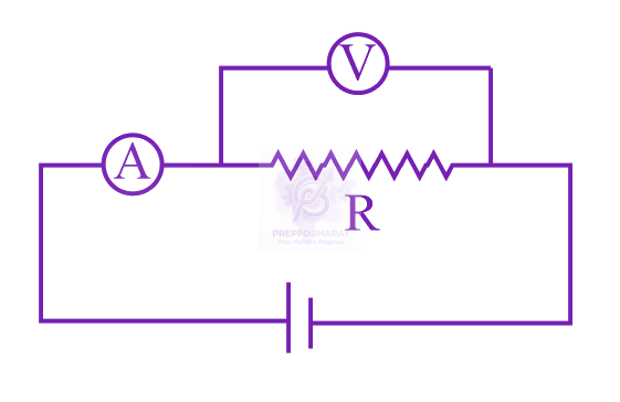
Sunlight of intensity $50 W{m}^{-2}$is incident normally on the surface of a solar panel. Some part of incident energy ($25%$) is reflected from the surface and the rest is absorbed. The force exerted on $1 {m}^{2}$ surface area will be close to $(c=3\times {10}^{8}m{s}^{-1})$
Space between two concentric conducting spheres of radii $a$ and $b$ $(b>a)$ is filled with a medium of resistivity $\rho$ . The resistance between the two spheres will be:
Shown in the figure is a shell made of a conductor. It has inner radius $a$ and outer radius $b$, and carries charge $Q$ . At its centre a dipole $\vec{p}$ is placed as shown then: 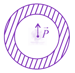
Seven capacitors, each of capacitance $2 \mu \mathrm{F},$ are to be connected in a configuration to obtain an effective capacitance of $\left(\frac{6}{13}\right) \mu \mathrm{F} .$ Which of the combinations, shown in figures below, will achieve the desired value?
One of the two identical conducting wires of length $L$ is bent in the form of a circular loop and the other one into a circular coil of $N$ identical turns. If the same current is passed in both, the ratio of the magnetic field at the centre of the loop $({B}_{L})$ to that at the centre of the coil $({B}_{C}),$ i.e. $\frac{{B}_{L}}{{B}_{C}}$ will be
Mobility of electrons in a semiconductor is defined as the ratio of their drift velocity to the applied electric field. If, for an $\text{N}$-type semiconductor, the density of electrons is ${10}^{19} {m}^{-3}$ and their mobility is $1.6 {m}^{2}{V}^{-1}{s}^{-1}$, then the resistivity of the semiconductor (since it is an $\text{N}$-type semiconductor contribution of holes is ignored) is close to:
Let a total charge $2Q$ be distributed in a sphere of radius $R,$ with the charge density given by $\rho (r)=kr,$ where $r$ is the distance from the centre. Two charges $A$ and $B$ , of $-Q$ each, are placed on diametrically opposite points, at equal distance, a, from the centre. If $A$ and $B$ do not experience any force, then:
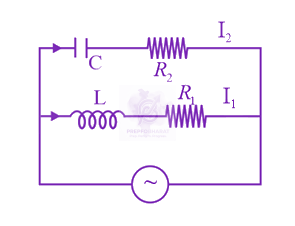 In the above circuit, $C=\frac{ \sqrt{ 3 } }{2} \mu F, {R}_{2} =20 \Omega , L=\frac{ \sqrt{ 3 } }{ 10} H$ and ${R}_{1} =10 \Omega .$ Current in $L\text{-}{R}_{1}$ path is ${I}_{1}$ and in $C-{R}_{2}$ path it is ${I}_{2} .$ The voltage of AC source is given by, V=200 2 sin( 100 t ) volts. The phase difference between ${I}_{1}$ and ${I}_{2}$ is:
In the given circuit the internal resistance of the $18V$ cell is negligible. If ${R}_{1}=400 \Omega , {R}_{3}=100 \Omega$ and ${R}_{4}=500 \Omega$ and the reading of an ideal voltmeter across ${R}_{4}$ is $5 V,$ then the value of ${R}_{2}$ will be: 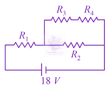
In the given circuit, the charge on $4 \mu F$ capacitor will be: 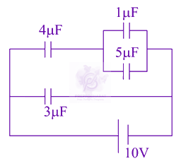
In the given circuit the cells have zero internal resistance. The currents (in amperes) passing through resistance ${R}_{1}$ and ${R}_{2}$ respectively, are: 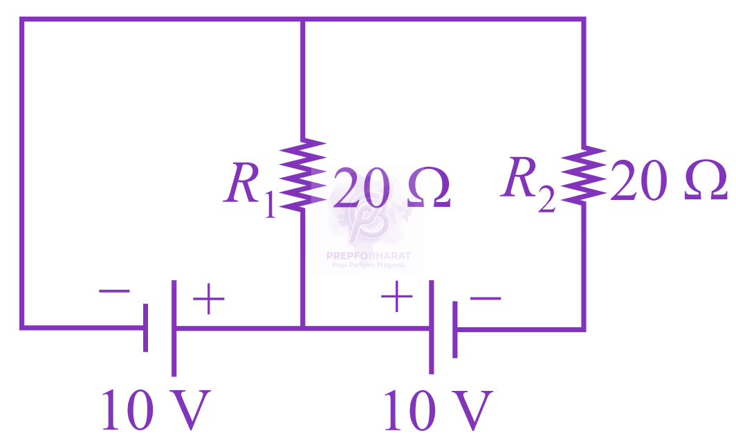
In the given circuit diagram, the currents, ${I}_{1}=-0.3 A, {I}_{4}=0.8 A$ and ${I}_{5}=0.4 A,$ are flowing as shown. The currents ${I}_{2}, {I}_{3}$ and ${I}_{6},$ respectively, are: 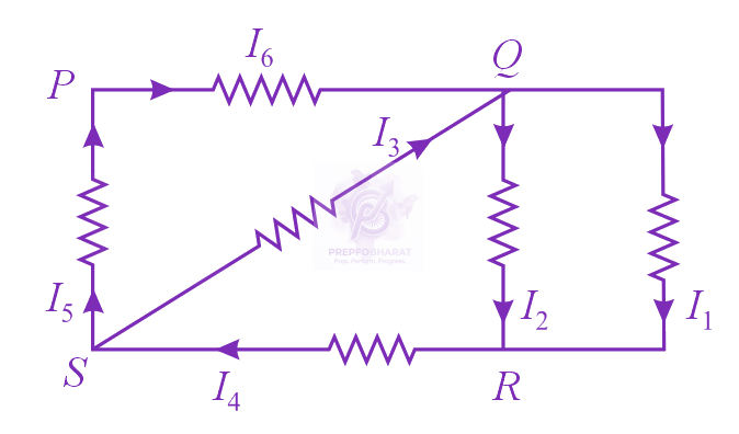
In the given circuit, an ideal voltmeter connected across the $10 \Omega$ resistance reads $2 V$ . The internal resistance $r$ , of each cell is: 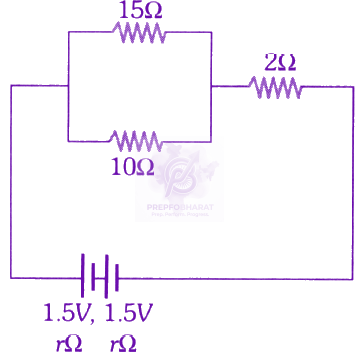
In the figure shown, what is the current (in Ampere) drawn from the battery? You are given: ${R}_{1}=15 \Omega , {R}_{2}=10 \Omega , {R}_{3}=20 \Omega , {R}_{4}=5 \Omega , {R}_{5}=25 \Omega , {R}_{6}=30 \Omega , E=15V$ 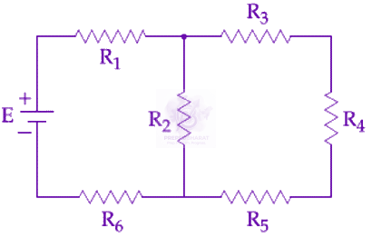
In the figure shown below, the charge on the left plate of the 10F capacitor is -30C. The charge on the right plate of the 6F capacitor is: 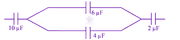
In the figure shown, a circuit contains two identical resistors with resistance $R=5 \Omega$ and an inductance with $L=2 mH.$ An ideal battery of $15V$ is connected in the circuit. What will be the current through the battery long after the switch is closed? 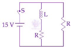
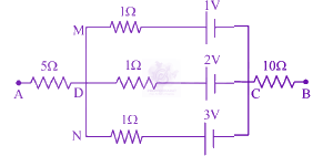
In the circuit shown, the potential difference between $\mathrm{A}$ and $B$ is