JEE Main Physics — Electromagnetism previous year questions with solutions.
Three charges $Q,+y$ and $+q$ are placed at the vertices of a right-angle isosceles triangle as shown below. The net electrostatic energy of the configuration is zero, if the value of $\mathrm{Q}$ is 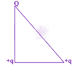
A parallel plate capacitor with square plates is filled with four dielectrics of dielectric constants ${K}_{1}, {K}_{2}, {K}_{3}, {K}_{4}$ arranged as shown in the figure. The effective dielectric constant $K$ will be: 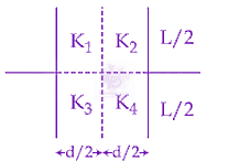
A coil of self inductance $10 mH$ and resistance of $0.1 \Omega$ is connected through a switch to a battery of internal resistance $0.9 \Omega$ . After the switch is closed, the time taken for the current to attain $80%$ of the saturation value is: $[ \mathrm{ln}5=1.6 ]$
Charges $-q$ and $+q$, located at $A$ and $B$, respectively, constitute an electric dipole. Distance $AB=2a$, $O$ is the mid point of the dipole and $OP$ is perpendicular to $AB$. A charge $Q$ is placed at $P$ where $OP=y$ and $y\gg 2a$. The charge $Q$ experiences an electrostatic force $F$. If $Q$ is now moved along the equatorial line to $P'$ such that $OP'=(\frac{y}{3})$ the force on $Q$ will be close to$(\frac{y}{3}\ll 2a)$ 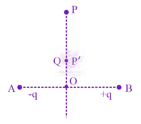
In an experiment, the resistance of a material is plotted as a function of temperature (in some range). As shown in the figure, it is a straight line. 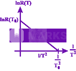 One may conclude that
In free space, a particle $A$ of charge $1 \mu C$ is held fixed at point $P$ . Another particle $B$ of the same charge and mass $4 \mu g$ is kept at a distance of $1 mm$ from $P.$ If $B$ is released, then its velocity at a distance of $9 mm$ from $P$ is: [Take $\frac{1}{4\pi {\epsilon }_{0}}=9\times {10}^{9} N {m}^{2} {C}^{-2}$ ]
The figure shows a capacitor of capacitance $C$ connected to a battery via a switch, having a total charge $Q$ on it, in steady-state. When the switch $S$ is turned from position $A$ to position $B$, the energy dissipated in the circuit is 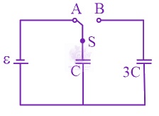
Three charges $+Q, q,+Q$ are placed respectively, at distance, $0,d/2$ and $d$ from the origin, on the $x$ -axis. If the net force experienced by $+Q,$ placed at $x=0,$ is zero, then value of $q$ is:
The actual value of resistance $R$ , shown in the figure is $30\Omega .$ This is measured in an experiment as shown using the standard formula $R=\frac{V}{I}$ , where $V$ and $I$ are the readings of the voltmeter and ammeter, respectively. If the measured value of $R$ is $5%$ less, then the internal resistance of the voltmeter is: 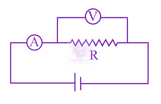
A circular coil having $N$ turns and radius $r$ carries a current $I.$ It is held in the $XZ$ plane in a magnetic field $B\hat{i}$ . The torque on the coil due to the magnetic field is:
The parallel combination of two air filled parallel plate capacitors of capacitance $C$ and $nC$ is connected to a battery of voltage, $V.$ When the capacitors are fully charged, the battery is removed and after that a dielectric material of dielectric constant $K$ is placed the two plates of the first capacitor. The new potential difference of the combined system is:
The electric field in a region is given by $\vec{E}=(Ax+B) \hat{i} ,$ where $E$ is in $N{C}^{-1}$ and $x$ is in metres. The values of constants are $A=20 SI$ unit and $B=10 SI$ unit. If the potential at $x=1$ is ${V}_{1}$ and that at $x=-5$ is ${V}_{2},$ then ${V}_{1}-{V}_{2}$ is
Two wires $A$ & $B$ are carrying currents ${I}_{1}$ and ${I}_{2}$ as shown in the figure. The separation between them is $d$ . A third wire $C$ carrying a current $I$ is to be kept parallel to them at a distance $x$ from $A$ such that the net force acting on it is zero. The possible values of $x$ are: 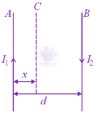
A thin ring of $10 cm$ radius carries a uniformly distributed charge. The ring rotates at a constant angular speed of $40\pi rad{s}^{-1}$ about its axis, perpendicular to its plane. Is the magnetic field its centre is $3.8\times {10}^{-9}T$ , then the charge carried by the ring is close to $({\mu }_{0}=4\pi \times {10}^{-7}N/{A}^{2}).$
A particle having the same charge as of electron moves in a circular path of radius $0.5 cm$ under the influence of a magnetic field of $0.5 T.$ If an electric field of 100 V/m makes it to move in a straight path, then the mass of the particle is (Given charge of electron $=1.6\times {10}^{-19}C$ )
Let a total charge $2Q$ be distributed in a sphere of radius $R,$ with the charge density given by $\rho (r)=kr,$ where $r$ is the distance from the centre. Two charges $A$ and $B$ , of $-Q$ each, are placed on diametrically opposite points, at equal distance, a, from the centre. If $A$ and $B$ do not experience any force, then:
A galvanometer having a resistance of $20 \Omega$ and 30 division on both sides has figure of merit 0.005 ampere/ division. The resistance that should be connected in series such that it can be used as a voltmeter upto 15 volt, is:
A current loop, having two circular arcs joined by two radial lines is shown in the figure. It carries a current of $10 A.$ The magnetic field at point $O$ will be close to: 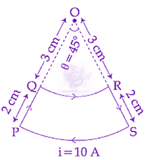
In the given circuit the cells have zero internal resistance. The currents (in amperes) passing through resistance ${R}_{1}$ and ${R}_{2}$ respectively, are: 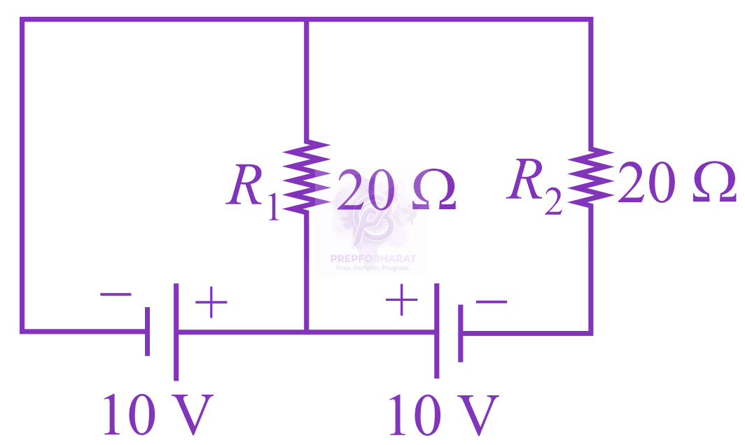
There is a uniform spherically symmetric surface charge density at a distance ${R}_{0}$ from the origin. The charge distribution is initially at rest and starts expanding because of mutual repulsion. The figure that represents best the speed $V(R(t))$ of the distribution as a function of its instantaneous radius $R(t)$ is:
A magnet of total magnetic moment ${10}^{-2}\hat{i} A{m}^{2}$ is placed in a time varying magnetic field, $B\hat{i}(\mathrm{cos}\omega t)$ where $B=1$ Tesla and $\omega =0.125 \mathrm{rad}{s}^{-1}$. The work done for reversing the direction of the magnetic moment at $t=1$ second, is:
Two very long, straight, and insulated wires are kept at ${90}^{o}$ angle from each other in $xy-plane$ as shown in figure. 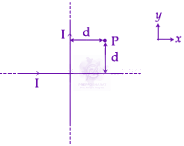 These wires carry currents of equal magnitude $I$ , whose direction are shown in the figure. The net magnetic field at point $P$ will be:
An insulating thin rod of length $l$ has a linear charge density $\rho (x)={\rho }_{0}\frac{x}{l}$ on it. The rod is rotated about an axis passing through the origin $(x=0)$ and perpendicular to the rod. If the rod makes $n$ rotations per second, then the time averaged magnetic moment of the rod is:
A moving coil galvanometer allows a full scale current of ${10}^{-4} A$ . A series resistance of $2 \times {10}^{4} \Omega$ is required to convert the galvanometer into a voltmeter of range $0-5 V$ . Therefore, the value of shunt resistance required to convert the above galvanometer into an ammeter of range $0-10 mA$ is: