JEE Main Physics — Electromagnetism previous year questions with solutions.
An alternating voltage $V(t)=220\mathrm{sin}(100\pi t)$ volt is applied to a purely resistive load of $50 \Omega$ . The time taken for the current to rise from half of the peak value to the peak value is:
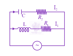 In the above circuit, $C=\frac{ \sqrt{ 3 } }{2} \mu F, {R}_{2} =20 \Omega , L=\frac{ \sqrt{ 3 } }{ 10} H$ and ${R}_{1} =10 \Omega .$ Current in $L\text{-}{R}_{1}$ path is ${I}_{1}$ and in $C-{R}_{2}$ path it is ${I}_{2} .$ The voltage of AC source is given by, V=200 2 sin( 100 t ) volts. The phase difference between ${I}_{1}$ and ${I}_{2}$ is:
The electric field of a plane electromagnetic wave is given by $\vec{E}={E}_{0}\hat{i}\mathrm{cos}(kz)cos(\omega t)$ The corresponding magnetic field $\vec{B}$ is then given by:
A $27 \mathrm{~mW}$ laser beam has a cross-sectional area of $10 \mathrm{~mm}^{2}$. The magnitude of the maximum electric field in this electromagnetic wave is given by: [Given permittivity of space $\epsilon_{0}=9 \times 10^{-12} \mathrm{SI}$ units, Speed of light $\left.\mathrm{c}=3 \times 10^{8} \mathrm{~m} / \mathrm{s}\right]$
The energy associated with electric field is $({U}_{E})$ and with magnetic field is $({U}_{B})$ for an electromagnetic wave in free space. Then:
The electric field of a plane polarized electromagnetic wave in free space at time $t=0$ is given by the expression $\vec{E}(x, y)=10\hat{j}cos(6x+8z)$. The magnetic field $\vec{B}(x, z, t)$ is given by ($c$ is the velocity of light.)
Find the magnetic field at point $P$ due to a straight line segment $AB$ of length $6 cm$ carrying a current of $5 A.$ (See figure) $({\mu }_{0}=4\pi \times {10}^{-7}{\mathrm{NA}}^{-2})$ 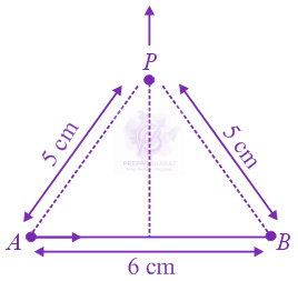
A moving coil galvanometer has resistance $50 \Omega$ and it indicates full deflection at $4 mA$ current. A voltmeter is made using this galvanometer and a $5 k\Omega$ resistance. The maximum voltage, that can be measured using this voltmeter, will be close to:
A parallel plate capacitor has $1\mu F$ capacitance. One of its two plates is given $+2\mu C$ charge and the other plate, $+4 \mu C$ charge. The potential difference developed across the capacitor is:
In the figure shown, a circuit contains two identical resistors with resistance $R=5 \Omega$ and an inductance with $L=2 mH.$ An ideal battery of $15V$ is connected in the circuit. What will be the current through the battery long after the switch is closed? 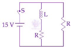
A magnetic compass needle oscillates $30$ times per minute at a place where the dip is $45^{\circ}$ and $40$ times per minute where the dip is $30^{\circ}$. If ${B}_{1}$ and ${B}_{2}$ are the net magnetic fields due to the earth at the two places respectively, then the ratio ${B}_{1}/{B}_{2}$ is approximately equal to
An electric dipole is formed by two equal and opposite charges $q$ with separation $d$ . The charges have same mass m. It is kept in a uniform electric field $E.$ If it is slightly rotated from its equilibrium orientation, then its angular frequency $\omega$ is:
The magnetic field of an electromagnetic wave is given by: $\vec{B}=1.6\times {10}^{-6}\mathrm{cos} (2\times {10}^{7}z+6\times {10}^{15}t) (2\hat{i}+\hat{j})\frac{Wb}{{m}^{2}}$ The associated electric field will be:
Figure shows charge $(q)$ versus voltage $(V)$ graph for series and parallel combination of two given capacitors. The capacitances are: 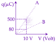
The resistive network shown below is connected to a $D.C.$ source of $16 V.$ The power consumed by the network is $4$ Watt. The value of $R$ is: 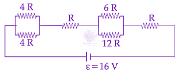
One of the two identical conducting wires of length $L$ is bent in the form of a circular loop and the other one into a circular coil of $N$ identical turns. If the same current is passed in both, the ratio of the magnetic field at the centre of the loop $({B}_{L})$ to that at the centre of the coil $({B}_{C}),$ i.e. $\frac{{B}_{L}}{{B}_{C}}$ will be
A power transmission line feeds input power at $2300 V$ to a step down transformer with its primary windings having $4000$ turns. The output power is delivered at $230 V$ by the transformer. If the current in the primary of the transformer is $5A$ and its efficiency is $90%$, the output current would be:
Given below in the left column are different modes of communication using the kinds of waves given in the right column. <table class="pyq-table"><tbody><tr><th>(1) Optical Fibre Communication</th><th>(P) Ultrasound</th></tr><tr><td>(2) Radar</td><td>(Q) Infrared Light</td></tr><tr><td>(3) Sonar</td><td>(R) Microwaves</td></tr><tr><td>(4) Mobile Phones</td><td>(S) Radio Waves</td></tr></tbody></table> From the options given below, find the most appropriate match between entries in the left and the right column.
A very long solenoid of radius $R$ is carrying current $I(t)=kt{e}^{-\alpha t}(k>0),$ as a function of time $(t\geq 0).$ Counterclockwise current is taken to be positive. A circular conducting coil of radius $2R$ is placed in the equitorial plane of the solenoid and concentric with the solenoid. The current induced in the outer coil is correctly depicted, as a function of time, by:
The mean intensity of radiation on the surface of the Sun is about ${10}^{8}W/{m}^{2}.$ The rms value of the corresponding magnetic field is closest to:
In the circuit shown, 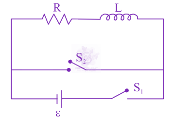 the switch $S_{1}$ is closed at time $t=0$ and the switch $S_{2}$ is kept open. At some later time $\left(\mathrm{t}_{0}\right)$, the switch $\mathrm{S}_{1}$ is opened and $\mathrm{S}_{2}$ is closed. the behaviour of the current I as a function of time ' $\mathrm{t}$ ' is given by:
As shown in the figure, two infinitely long, identical wires are bent by ${90}^{o}$ and placed in such a way that the segments $LP$ and $QM$ are along the $x$ - axis, while segments $PS$ and $QN$ are parallel to the $y$ - axis. If $OP=OQ=4cm,$ and the magnitude of the magnetic field at $O$ is ${10}^{-4} T,$ and the two wires carry equal currents (see figure), the magnitude of the current in each wire and the direction of the magnetic field at $O$ will be $({\mu }_{0}=4\pi \times {10}^{-7}N{A}^{-2}):$ 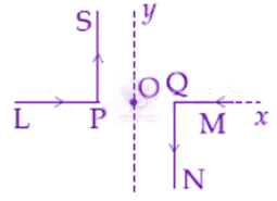
The magnetic field of a plane electromagnetic wave is given by $\vec{B}={B}_{0}\hat{i}[cos(kz-\omega t)]+{B}_{1}\hat{j}cos(kz+\omega t)$, where ${B}_{0}=3\times {10}^{–5} T$ and ${B}_{1}=2\times {10}^{–6} T$. The $\mathrm{RMS}$ value of the force experienced by a stationary charge $Q={10}^{–4} C$ at $z=0$ is closest to
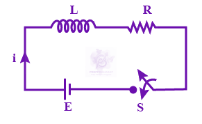
Consider the LR circuit shown in the figure. If the switch S is closed at $t=0$ then the amount of charge that passes through the battery between $t=0$ and $t=\frac{L}{R}$ is: